This time we’re working on the rear panel to finish installing TA7MNA’s battery and audio board.
Not much to say, I think the photos are pretty self-explanatory.
⚠️ 2025-11-16 — improved version with better BMS and PowerDelivery/QuickCharge charging module ⚠️
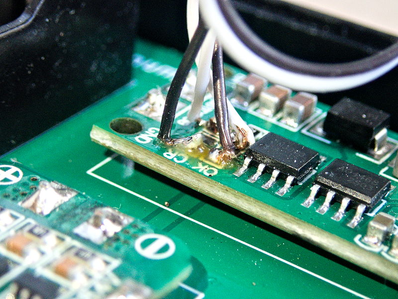
The two LEDs are moved to the rear panel
I desoldered the two SMD LEDs that indicate the charge status and replaced them with conventional LEDs for which I have clips.
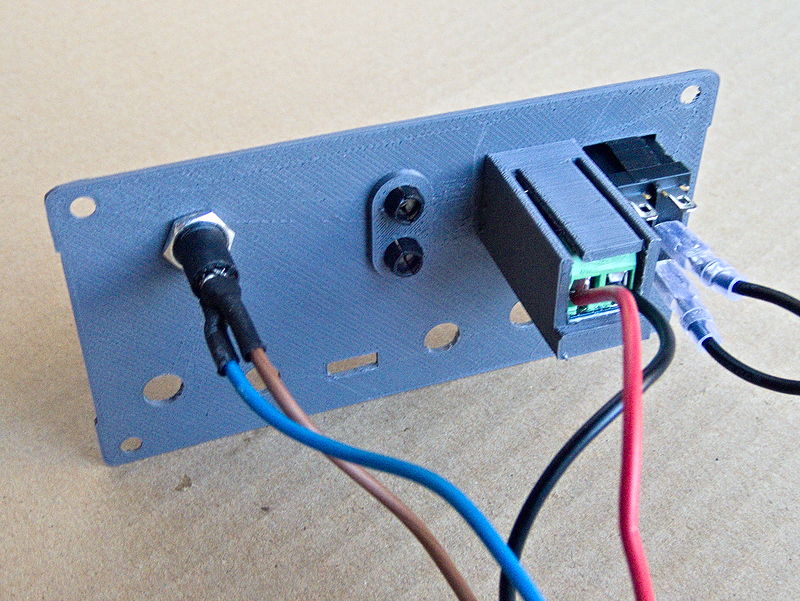
Inside of the rear panel
The rear panel design is simple, and printing is not difficult. I made a rough support for the PD trigger module.
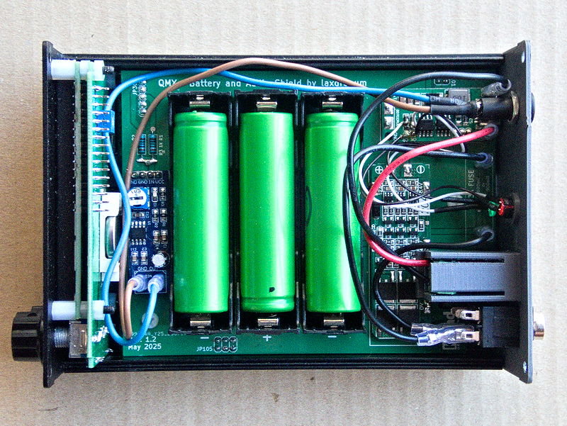
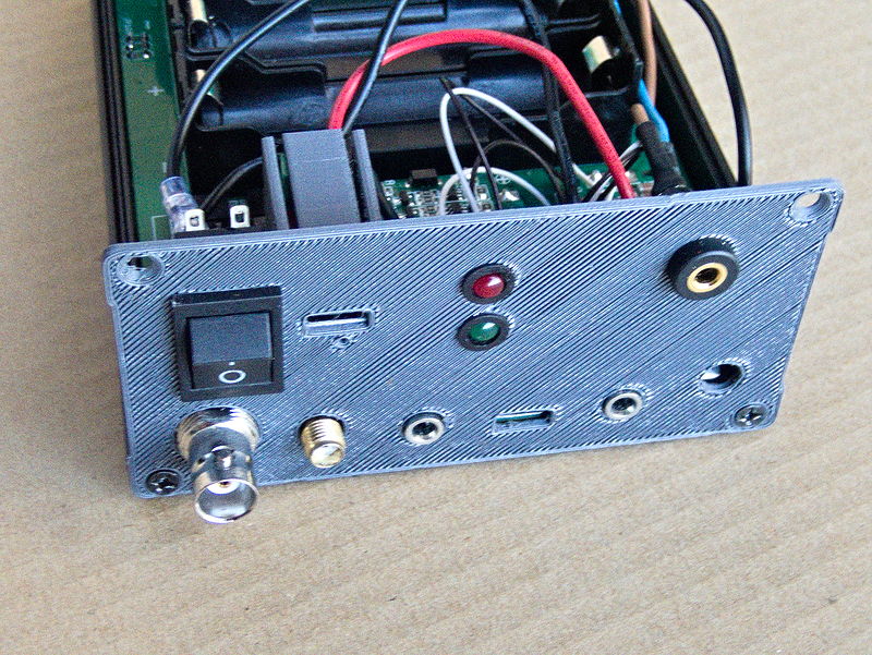
View from above
I misread the electronic circuit. I was convinced that the fuse was located between the BMS and the power connector of the QMX, but in fact it also concerns the charger, so my DPDT switch no longer makes sense (I wanted to be able to choose between powering or charging with the two positions, but unfortunately this is not possible).
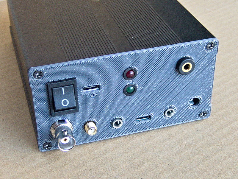
View from rear
⚠️ 2025-11-16 — improved version with better BMS and PowerDelivery/QuickCharge charging module ⚠️